Live Switch
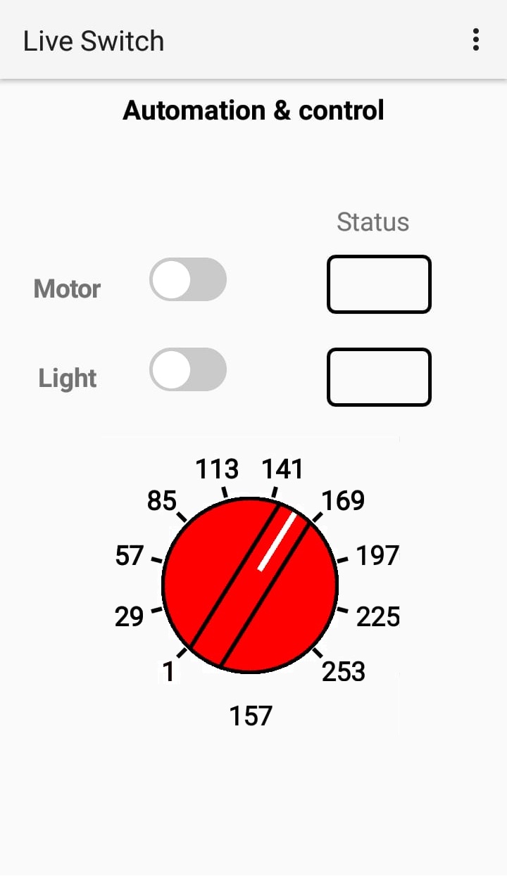
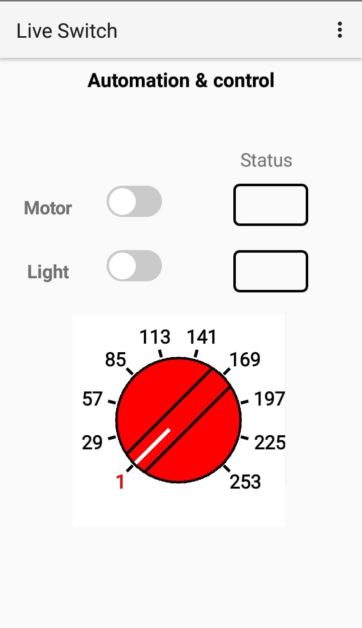
Live Switch is an IoT app used to turn ON and OFF devices, display the status of I/O pins and vary the PWM value on the local network without using an internet connection. It has customized network values (i.e., IP address, Port number, and PWM resolution), labels and title. It uses with any ESP8266 or ESP32 development board. The code is mentioned for ESP8266 node MCU, You can customize the I/O pins of your choice, However, For a PWM channel u have to select the specific PWM pin.

Connecting Live Switch with ESP8266
ESP8266 is a WiFi device for an IoT applications. It has various models with general purpose and special purpose I/Os. which includes digital I/O, an Analog input, PWM outputs, SPI control etc, which can be used for many apps. currently the code given below is copatible with Live switch app.Detailed introuduction of ESP8266
To connect ESP8266 or any equivalent hardware with Live switch app, the code given below must be modified in Arduino IDE (i,e., SSID, password and port address ..default is 82). once the Wifi credentials are confirmed the code can be uploaded into ESP8266 with USB cable.(make sure this code is only for ESP8266, so it will not work on ESP32). once the ESP is connected with your WiFI router, it will show IP address in sserial console, check that IP and insert it into Live switch app.
It is better idea to configure the static IP into wifi router so that each time ESP gets same IP.
Header files used
This code is compatible with ESP8266 only, For simple coding first two header files are needed but as this code has Over The Air(OTA) feature so additional 4 headers files are used. OTA is the feature where a user can reprogram an ESP module with wifi/ local network connection from arduin IDE, without using a USB cable.
#include "ESP8266WiFi.h"
  #include "ESP8266mDNS.h"

#include "WiFiClient.h"
#include "ESP8266WebServer.h"
#include "WiFiUdp.h"
#include "ArduinoOTA.h"
Router credentials
Change these credentials as per your requirements.
const char* ssid="Network";    // Wifi network SSID
const char* password ="12345678e";  // Wifi network password
ESP8266WebServer server(82);
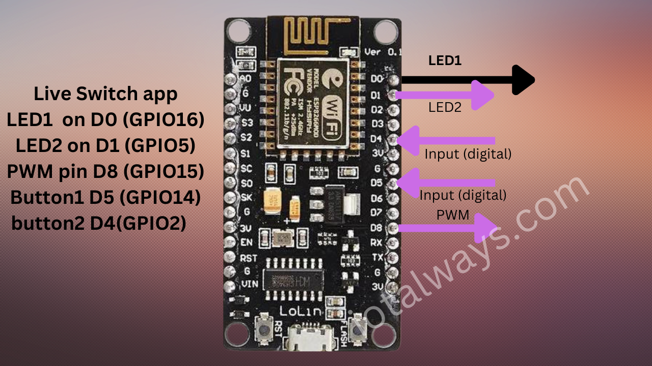
Define I/O pins
change I/O pins of your own choice..
#define LED1 16           //D0 pin of Nodemcu
#define LED2 5
#define PWMpin 15
#define button1 14
#define button2 2
Check Input pins
This code will check the inputs from ESP module and display the status on live switch app with green and Red LED .
void checkInputs() {
  String X;
  if ((digitalRead(button1) == LOW) && (digitalRead(button2) == LOW))
  {
    X="00";
  } else if ((digitalRead(button1) == HIGH) && (digitalRead(button2) == LOW))
  {
    X="10";
    } else if ((digitalRead(button1) == LOW) && (digitalRead(button2) == HIGH))
  {
    X="01";
  } else if ((digitalRead(button1) == HIGH) && (digitalRead(button2) == HIGH))
  {
    X="11";
  }
server.send(200, "text/html", X); //Send web page
}
Vary PWM signal
This PWM variable Knob is available in live switch app, varying the knob will change the value of PWM pin defined in ESP module, This value isi customized, the resolution can be set according with the hardware, currently 8 bit is used.
void PWMout() {
 String pwm_state = server.arg("PWM");
 Serial.println(pwm_state);
int x = pwm_state.toInt();
analogWrite(PWMpin, x);
delay(100);
server.send(200, "text/html", pwm_state);
}
Handle Outputs, controled from app
This code will turn ON or OFF I/Os on ESP8266,controlled from Live Switch app buttons.
void handleLED() {
 String ledState = "OFF";
 String t_state = server.arg("LED"); //Refer  xhttp.open("GET", "iotalways.com?LED="+led, true);
 Serial.println(t_state);
 if(t_state == "1")
 {
  digitalWrite(LED1,HIGH); //LED ON
  ledState = "ON"; //Feedback parameter, Optional
 }
 else if (t_state == "0")
 {
  digitalWrite(LED1,LOW); //LED OFF
  ledState = "OFF"; //Feedback parameter
 }
 else if (t_state == "2")
 {
  digitalWrite(LED2,HIGH); //LED ON
  ledState = "ON"; //Feedback parameter
 }
 else if (t_state == "3")
 {
  digitalWrite(LED2,LOW); //LED OFF
  ledState = "OFF"; //Feedback parameter
 }

 server.send(200, "text/plane", ledState); //Send web page
}
define the mode of Pins.
Live switch app has 5 controlleble I/O's, this setup section defines all modes of pins, establishes the wifi conenction, establishes OTA features and handles servers communication between app and hardware.
void setup() {
pinMode(LED1, OUTPUT);
pinMode(LED2, OUTPUT);
pinMode(PWMpin, OUTPUT);
pinMode(button1, INPUT);
pinMode(button2, INPUT);

WiFi connection and other Serial parameters
Connects the WIfif and Show the IP on Serial Port.
WiFi.begin(ssid, password);
Serial.begin(9600);
WiFi.setHostname("Live Swtich");
ArduinoOTA.setHostname("switch");
while (WiFi.status() != WL_CONNECTED) {
delay(500);
Serial.print(".");
}
Serial.print("IP Address: ");
Serial.println(WiFi.localIP());
WOTA enable
Connects with OTA Handler and enable the fucntionality.
Serial.println("OTA message");
ArduinoOTA.onStart([]() {
String type;
if (ArduinoOTA.getCommand() == U_FLASH) {
type = "sketch";
} else { // U_FS
type = "filesystem";
}
Serial.println("Start updating " + type);
});
ArduinoOTA.onEnd([]() {
Serial.println("\nEnd");
});
ArduinoOTA.onProgress([](unsigned int progress, unsigned int total) {
Serial.printf("Progress: %u%%\r", (progress / (total / 100)));
});
Server settings
Never modify these settings or labels. these are used to synchronize the app. and start the server. OTA is password protected, You can change the password of your choice.
//*******************8Handle root*************************************
//server.on("/", handleRoot);
server.on("/iotalways.com", handleLED);
server.on("/readInputs", checkInputs);
server.on("/electronixforu.com", PWMout);
server.begin(); //Start server
Serial.println("HTTP server started");
ArduinoOTA.setPassword((const char *)"123");
ArduinoOTA.begin();
}
Loop
You can modify it according to your requirements. However no coding needed in loop section.
void loop() {
ArduinoOTA.handle();
server.handleClient();
}